
Conventional on-site systems are the most common and the simplest on-site wastewater disposal systems. Installed properly, conventional systems are very reliable and require minimal maintenance.

For area-fill systems that meet the requirements of 15ANCAC 18A.1957(b)(l)(A), the lowest LTAR for the applicable soil group of the most hydraulically limiting soil horizon within 18 inches of the naturally occurring soil surface or to a depth of one foot below the trench bottom, whichever is deeper, must be used to design the system.
The LTAR values for Group I soil area-fill systems are reduced to spread the flow of the effluent over a larger area over these very permeable soils so that the effluent receives adequate treatment. There are two exceptions to the LT AR shown for Group I soils (Table 4.6.1) when using fill systems:
The LTAR cannot be greater than 1.0 gallon per day per square foot for gravity distribution, or
The LTAR cannot be greater than 0.5 gallons per day per square foot for low-pressure pipe systems installed on sites with at least 18 inches of Group I soils below the naturally occurring soil surface or to a depth of one foot below the trench bottom, whichever is deeper.
Reference
15A NCAC 18A.1957(b)(l)(D)
From the North Carolina Onsite Guidance Manual
The depth where restrictive horizons are located is important when determining the suitability of a site. Because restrictive horizons retard or stop water or wastewater flow, the presence of these horizons, if they are too close to the soil surface, can disqualify a site for on-site system installation.
Six factors must be evaluated for installation of an on-site system. These factors determine what type of on-site system best fits the site and how well the system will perform. The following section first discusses the six site and soil evaluation factors and how the site can be classified. Then each evaluation factor is presented in detail, explaining what the factor is and how to evaluate it. NOTE: This applies to design wastewater flows of 3,000 gpd or less.
In the state of North Carolina six factors must be evaluated to determine the suitability of a site for on-site system installation. The six factors are:
1. slope and landscape position,
2. soil morphological characteristics,
3. soil wetness,
4. soil depth,
5. restrictive horizons, and
6. available space.
Classification of Factors
After the site and soil evaluation, the local health department will compile the information and classify each factor as SUITABLE (S), PROVISIONALLY SUITABLE(PS), or UNSUITABLE (U), for ground absorption sewage effluent treatment and disposal (fable 4.5.1).
Overall Site Suitability
After each of the factors are classified as S, PS, or U, the overall site classification is determined by the most limiting factor that cannot be corrected by design or site modifications. For example, the soil wetness factor is U due to soil wetness at a depth of 32 inches in a loamy soil. The site may then be reclassified as PS, with the trench bottom installed no deeper than 20 inches.
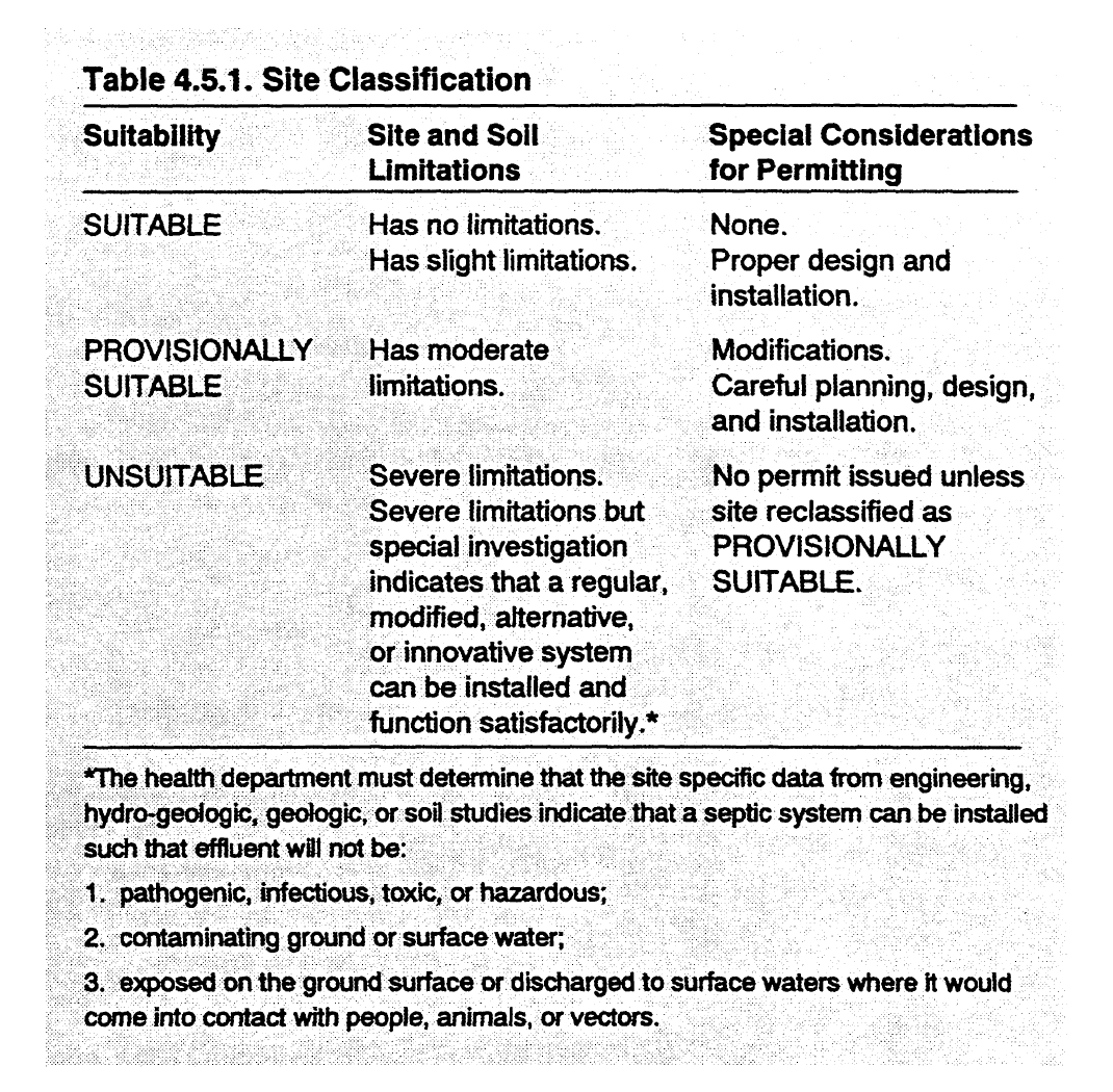
Site Classification
Types of on-site systems allowed for each site classification.
A site classified as SUIT ABLE receives a permit for on-site system installation with few restrictions. A permit with more restrictions is issued for a site classified as PROVISIONALLY SUITABLE. No permit is issued for UNSUITABLE sites unless the site is reclassified as PROVISIONALLY SUIT ABLE. The three types of site classification are described in the following list.
1. A conventional on-site system can be installed on a SUIT ABLE site with greater than 4 feet to any restrictions. This system could have 2 feet of backfill over the top of the crushed rock in the trench and the trench bottom would be at least 12 inches above any unsuitable soil layer. See Figure 4.5.1 for a diagram of a conventional trench.
2. A modified on-site system would have to be installed on a site permitted as PROVISIONALLY SUIT ABLE. For example, in a conventional modified system the distance between the soil surface and top of the crushed stone in the trench would only be 12 inches instead of 24 inches. See Figure 4.5.1 for a diagram of one type of modified conventional trench.
3. If a soil layer with unsuitable characteristics is located within 36 inches of the surface, the soil is classified as UNSUITABLE. With further investigation and if certain site modifications are made or if certain alternative on-site systems are used, the site may reclassified as PROVISIONALLY SUIT ABLE. Chapter 7 gives details about alternative systems .

Placement of modified conventional trenches in the soil
Reclassifying UNSUITABLE Sites.
Sites can be reclassified from UNSUITABLE to PROVISIONALLY SUIT ABLE because of soil wetness or restrictive horizons if the following conditions are met:
1. Soils are Group I or II with SUITABLE structure and clay mineralogy.
2. Restrictive horizons, if present, are less than 3 inches thick or less than 12 inches from the soil surface.
3. Site modifications can be made so that there is at least one foot of naturally occurring soil between the trench bottom and saprolite, rock, or any soil horizon unsuitable because of structure, clay mineralogy, and wetness. A lowpressure pipe system must be used if the separation between the bottom of the nitrification trench and any soil wetness condition is less than 18 inches and if more than 6 inches of this separation consists of Group I soils.
4. Easements are recorded and have adequate width for access to maintain drainage systems serving two or more lots.
5. Maintenance of the drainage system is made a condition of any permit issued for the use or operation of a sanitary sewage system.
6. Drainage can be used in other types of soil as long as the appropriate engineering, bydrogeologic, geologic, or soil studies indicate that:
a ground absorption system can be installed so that the effluent will be non-pathogenic, non-infectious, non-toxic, and non-hazardous;
the effluent will not contaminate ground water or surface water; and
the effluent will not be exposed on the ground surface or be discharged to surface waters where it could come in contact with people, animals, or vectors.
From the North Carolina Onsite Guidance Manual
The key to installing a reliable on-site system that minimizes pollution and disease is to identify suitable locations with a thorough site and soil evaluation. The evaluation determines suitability or points out site limitations. Only after a site evaluation has been completed can the proper on-site system be designed.
This section provides guidelines for a thorough site and soil evaluation.
On-site systems must: (1) protect public health, and (2) minimize environmental impacts. To accomplish these goals, the state of North Carolina uses a site and soil evaluation to determine the suitability of a location for an on-site system and the type of system that can be installed.
This section discusses the purpose and offers guidelines for making a proper site and soil evaluation for a proposed on-site system.
The purpose of the site assessment is to understand the soil system and the hydrology of the site, to predict wastewater flow through the soil and into subsurface materials, and to design an on-site system to match the soil system and the hydrology of the site. The site and soil evaluation helps to predict how an onsite system will function at a site. How well the system functions depends on the soil's ability to absorb the wastewater, the probable flow paths of water from the site, and the treatment received by the wastewater.
The comprehensive site and soil evaluation used in North Carolina requires considerable expertise by the site evaluator. The site evaluator must have substantial knowledge about soil science, geology, sanitary engineering, and environmental health. Guidelines for a site evaluation are discussed below.
The ten guidelines for a site evaluation can be grouped into the three components of a site evaluation:
collecting information before the site visit,
assessing the site and soil at the location, and
recording site evaluation data for system design and relaying the information to the designer of the system and the applicant.
*This section, Site and Soil Evaluation, was written from existing unpublished materials by Michael T. Hoover (Department of Soil Science, North Carolina State University).
Collecting information before the site visit.
This component of site evaluation consists of preparation. Preparation includes learning about the sites and soils in the region and knowing what types of on-site wastewater systems can best fit a situation along with gathering information about the site to be evaluated.
FIRST GUIDELINE. Know the rules and know how to collect the needed information. The Laws and Rules for Sewage Treatment and Disposal Systems are established by the Commission for Health Services to protect public health and minimize the environmental damage from on-site systems. These rules provide performance criteria for on-site systems and consider the allowable risks to the environment and public health from constituents of the wastewater, such as bacteria, viruses, nitrate, phosphorus, and other pollutants. The rules also provide the legal support for a site and soil evaluation and set the standards for site suitability.
The standards in the rules determine the amount and level of information ihat will be collected for each site. An initial site assessment will determine the level of detail for the site investigation and the type of data that should be collected. For example, a site with relatively flat slope and deep, well-drained loamy soils will require less investigation than a site with a more complex slope and several different soil profiles.
SECOND GUIDELINE. Determine the wastewater flow rate and characteristics. Information on wastewater quantity and quality is used to determine the initial size and type of on-site system to be installed at a particular site. The information for determining wastewater quantity and quality can be obtained from the application for an Improvement Permit.
The type of activity and size of facility that the on-site system will serve determine the daily flow and the peak flow of wastewater, or wastewater quantity. Likewise, the strength of the wastewater, or wastewater quality, is determined by the activities in the facility and, to some degree, by the size of the facility and how and when the wastewater is created.
Wastewater quantity and quality affect the level of detail required for a site evaluation. For instance, a site proposed for treatment and disposal of wastewater from a school designed for 400 students would require a more extensive site evaluation than a system for a two-bedroom home.
THIRD GUIDELINE. Review preliminary site information. Existing, published information will help the evaluator understand the types of soils and their properties and distribution on the landscape.
Published documents, such as soil survey reports; soil catena diagrams; and geologic, topographic and plat maps should be used for initial information about the site.
Warning: soil survey maps are good for planning, initial decision making, and helping you understand what to expect when you visit the site. However, they are not detailed enough to make siting recommendations. A field investigation is necessary for a proper site and soil evaluation. There is NO substitute for field investigations.
FOURTH GUIDELINE. Understand the septic system design options. Site evaluators must understand how on-site systems function in order to assess tradeoffs in design options. Additionally, the type of site investigation will also be determined by the system design options appropriate to the particular location. For instance, a different type of site investigation would be required for a modified conventional system using ground water interceptor drains than for a conventional on-site system.
The on-site system must be designed to allow a sufficiently deep aerobic zone beneath the treatment and disposal field to properly treat the wastewater before it enters the ground water.
Major design options include: the depth of the trench bottom or infiltrative surface; the loading rate used for sizing the system at the site; and the type of distribution system, such as gravity or pressure distribution and parallel or serial distribution.
The use of pretreatment options may be needed at the site.
Assessing the site and soil at the location.
FIFTH GUIDELINE. View the on-site system as part of the soil system and the hydrologic cycle. Typically, on-site systems serving single-family homes do not add enough water to the site to substantially change the site's hydrology.
SIXTH GUIDELINE. Predict wastewater flow through the soil and the underlying materials. The soil morphological evaluation and landscape evaluation are important in predicting flow paths and rate of wastewater movement through the soil and underlying materials. These two evaluations are used for on-site systems in North Carolina because landscape position and soil morphology greatly influence wastewater flow from the site.
Using the soil morphological characteristics, it can be determined whether water flow through the soil will occur primarily as vertical movement or as lateral movement in the horizontal direction.
Also, the soil morphological characteristics are used to estimate the long-term acceptance rate, or LTAR. This estimate of LTAR will determine the size of the area you must investigate. For example, if the first estimate ofLTAR for a site is 0.1 gallons per day per square foot (gpd/ft2) then you will need to evaluate four times the amount of land area than if the estimated LTAR had been 0.4 gpd/ft2 - For LTAR calculations see section 4.6.
Site and soil evaluations result in a more reliable prediction of wastewatermovement than a percolation or "perc" test. The perc test estimates saturated hydraulic conductivity by filling a borehole with water and measuring how quickly the water level falls. North Carolina formerly used the perc test to evaluate sites for on-site systems, but it has been shown that the perc test technique is inaccurate and unreliable for determining wastewater flow. Therefore, North Carolina discontinued the use of the perc test for evaluating sites for on-site systems several years ago.
SEVENTH GUIDELINE. Determine if additional informati.on is needed from the site. Site and soil conditions and the type of on-site system being considered determine whether additional evaluation is required. Some additional evaluations that may be required are: ground water mounding analysis, drainage analysis, hydrogeologic testing, linear loading rate evaluation, and hydraulic conductivity measurements.
For instance, if a large system serving a school is proposed at a location with ground water within 7 to 10 feet of the soil surface, you would want to identify whether there are any horizons limiting flow. Saturated hydraulic conductivity measurements in the least permeable horizon followed by ground water mounding analyses would be beneficial. This analysis helps predict whether unsaturated, aerobic conditions will still be present beneath the treatment and disposal field after operation begins and if ground water mounding occurs beneath the system.
In another example, if the soil is poorly drained, but sandy and located on a flat site, it may be possible to modify the seasonal high water table by using drainage. However, since the site is flat, additional investigations must be used to determine whether there is adequate elevation drop from the site to the proposed drainage outlet. This soil and site evaluation is necessary since drainage would not work effectively if there was not an adequate outlet available.
EIGHTH GUIDELINE. Assess the treatment potential of the site. The treatment potential of the site depends on the degree of soil aeration and the rate of flow of the wastewater through the soil. Wastewater is treated more effectively in wellaerated soils where wastewater flow is slow, which allows adequate adsorption and degradation of undesirable chemical and biological constituents. Thus, soil depth is crucial in determining the treatment potential of the site because there is a longer flow path through deeper soils. The longer flow path means more contact with the soil and soil organisms, and more time for degradation of pollutants.
In North Carolina, there must be 12 inches or more of separation between the bottom of the trench and any limiting soil condition such as restrictive horizons, wetness conditions, or bedrock. This separation provides a reasonable flow path and contact time for the pollutants to be removed.
The one exception is for Class I soils, which need a distance of 18 inches or more between the trench bottom and restrictive horizons, soil wetness conditions, or bedrock. These soils have a greater separation distance because wastewater flows more rapidly through them. The 18-inch separation provides more contact time for pollutant removal in these highly permeable soils.
NINTH GUIDELINE. Evaluate the site's environmental and public health sensitivity. Installing on-site systems in close proximity to community wells, near shellfish waters, in sole-source aquifer areas, or other sensitive areas may raise concerns regarding environmental and public health issues. When there are special environmental or public health concerns about a site, it may be necessary to obtain additional site information or perform certain evaluations to determine the degree of impact of the on-site system. In such cases adequate documentation must be kept to show that the site evaluation included the area of concern.
For instance, concerns about public health may be raised when large on-site systems are located adjacent to community wells. Here a detailed assessment of the ground water flow system is warranted. It is essential to determine whether the plume of wastewater from the treatment and disposal field will be intercepted by the cone of depression of the community well. If the cone of depression of the well is affected, then additional pretreatment of the wastewater may be needed to minimize any chance of polluting the community well.
Recording site evalua.tion data/or system design and relaying the information to the designer.
This component requires the site evaluator to communicate information gathered from the site evaluation to the person designing the system so that a proper design can be made.
TENTH GUIDELINE. Provide the system designer with soil/site descriptions and your recommendations. Based on the information gathered about the facility, and the actual site and soil evaluation, the last step is to suggest loading rates, highlight site and design considerations, and to point out special concerns in designing the on-site system.
The site evaluator should rank each site for the type of system that can be installed and provide specific soil and site data that will enable selection of the most feasible design options for the site. It is not enough to just provide the recommended loading rate or design. You must provide the data upon which these decisions are based.
In many cases, a single site and soil evaluation will be all that is necessary to design an appropriate system. However, on some sites, after collecting information about the site prior to and during the site visit, the evaluator may need additional information to determine the suitability of the site and the type of onsite system to be installed.
The process of data collection, evaluation, and design is often an iterative process. This means that the whole process is repeated several times, where each time new information or a new design is tried until a design is found that will fit the site. Some sites may require many repetitions before the final selection of an appropriate on-site system is made.
From the North Carolina Onsite Guidance Manual
Landscape position and slope affect water movement across a site and through the soil. Thus, an understanding of slope and landscape position is critical in predicting water flow and site suitability for on-site system placement. Wellpositioned on-site systems ensure that water is drained away from the site and that an adequate depth of aerated soil (12 - 18 inches) is maintained under the treatment and disposal trenches.
Relief, which includes slope and landscape position, is one of the five soil-forming factors that, along with climate, organisms, parent material and time, affect the soil's characteristics. Relief bas a pronounced effect on the soil type and depth, characteristics that are critical in determining the suitability of a site for the placement of an on-site system.
Slope and topography.
Slope refers to the inclination of the land surface whereas topography refers to the physical features of an area of land, especially the surface configuration.
The topography of an area can be described as hilly, mountainous, flat, or as a coastal plain, foothills, piedmont terrain, plateau, or mountain ridges. Topography can be simple, such as in areas with smooth land surfaces, or complex, such as in areas that have abruptly irregular land surfaces. For example, contours of elevation, and the shapes of hills, mountains, valleys, ravines, streams, and rivers are shown on a topographic map.
Conventional on-site systems can be installed on slope from 0-65%. The shape of the slope at a specific site is also important. For example, a site on a slope may have an outward or convex curve, which is a good placement site, or an inward or concave curve, which is a poor placement site.
Landscape position.
Landscape position is the specific position on a topographic feature. For example, an area may have a billy topography and the landscape position of an on-site system may be at the bottom of one hill in the area. The landscape position of the treatment and disposal field is critical to the performance of an on-site system.
Slope and landscape position.
Figure 4.4.24 shows the different landscape positions: interfluve or ridgetop, shoulder slope, side slope, foot slope, and toe slope.
1. The interfluve, or ridgetop, is the flat area between streams. If the distance between the streams is large then the area is called the interfluve. Conversely, if the distance is small then the flat area is the ridgetop.
2. The shoulder slope is the landscape position adjacent to the interfluve, where the flat areas begin to break into a slope. This slope is concave and water runs off without accumulating in the soil.
3. Side slopes have nine distinct slope types: linear-linear, linear-convex, linearconcave, convex-linear, convex-convex, convex-concave, concave-linear, concave-convex, and concave-concave (Figure 4.4.25).
Linear slopes follow a straight line down the slope but may be flat or curve across the slope, in the horizontal direction. If the land follows a straight line down the slope and across the slope, then it is called linear/ linear. If the linear slope curves outward across the slope it is linear/ convex, and if it curves inward it is linear/concave.
More runoff flows away from the site on linear/linear and linear/convex slopes than on linear/concave slopes. This means that less water accumulates in the soil on linear/linear and linear/convex slopes than on linear/concave slopes.
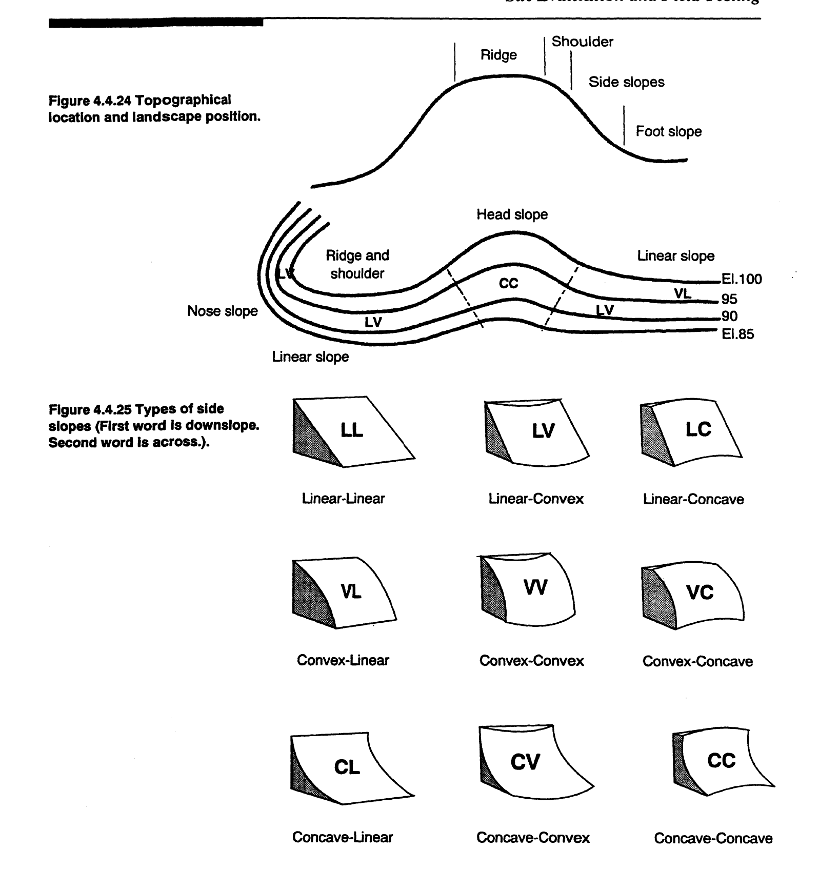
Topographical location and landscape position
4. Toward the bottom of the slope is the foot slope and the flatter toe slope. This is where colluvium, soils formed from debris moving down the hill, and alluvium, soils formed from deposits of sediment from streams, are found. The toe and foot slopes have a concave shape in the vertical direction and are often poorly drained.
Because slope and landscape position have pronounced effects on the soil type, soil depth, and drainage, these factors are extremely important in site evaluations for on-site systems. However, slope and landscape position must always be evaluated at each site because soil conditions and drainage differ in different regions. The following points indicate how slope and landscape positions should be used for site evaluations.
Land with a uniform slope less than 15% is considered to be SUIT ABLE for on-site systems.
If the topography is such that the land has a uniform slope between 15 and 30%, then that land is considered PROVISIONALLY SUITABLE for on-site systems.
For land with a slope greater than 30%, the land is classified as UNSUITABLE unless an investigation shows that a modified conventional on-site system can be installed properly as under rule 15A NCAC lSA.1956.
Slopes greater than 65% are always classified as UNSUITABLE.
Topography where there are complex shapes to the slopes or many gullies and ravines cutting the slopes is considered UNSUITABLE for on-site systems.
Depressions, or bowl-shaped indentations in the land surface, usually are inappropriate sites for on-site systems and are classified as UNSUITABLE. Depressions collect water and are generally wetter than the surrounding soils, making them UNSUITABLE. However, if the site complies with other requirements and is approved by the local health department, the site may be considered SUITABLE.
Toe slopes, foot slopes, head slopes, and depressional areas are difficult landscape positions for siting septic systems because these locations are frequently not sufficiently drained.
Occasionally, there is a difference in the suitability of the same landscape position in the three geographic regions in North Carolina (fable 4.4.12). This is because the same landscape position in different regions has differing drainage. For example, although the interfluve position is an excellent location for on-site systems in the Piedmont and Mountains, it is a poor site in the Coastal Plain. Because the Coastal Plain is relatively flat and also because there is a restrictive layer that causes a shallow ground water table, soils in the interfluve region of the Coastal Plain are poorly drained and are generally UNSUITABLE for on-site systems. See Figure 4.2.3 for an illustration of this characteristic.

Landscape Position and On-Site System Siting Potential
From the North Carolina Onsite Guidance Manual
Hydrologic parameters describe the way water moves through soil and are critical components in siting on-site systems.
Saturated hydraulic conductivity is the rate at which water moves through a saturated soil. In a saturated soil, all of the pore voids are filled with and transmitting water. The rate of flow through a soil is dependent on the sizes, number, and interconnectedness of the voids in the soil. The number of voids, their size, and spacing depend on numerous soil characteristics such as texture, mineral content, structure, biological activity, and horizon placement. Saturated hydraulic. conductivity will vary between soil horizons within the same profile and from location to location.
Saturated hydraulic conductivity is important in on-site systems. This parameter can help the designer determine the volume of wastewater that the site can transmit in a given time when the soil is saturated. On-site treatment and disposal fields are not supposed to become saturated, but under some conditions, such as during wet winter months, the ground may become saturated. Thus, the saturated hydraulic conductivity can determine how a system will perform under worst-case conditions.
The measure of water movement through a saturated soil has the units of distance/time and is given the symbol Ksat.
Each soil horizon has its own individual Ksat, which normally varies greatly from the Ksat of other horizons in the same profile.
Based on measurements of saturated hydraulic conductivity, soils are grouped into six classes, from very low to very high hydraulic conductivity. See Table 4.4.11 for a complete listing of saturated hydraulic conductivity classes.
If saturated hydraulic conductivity measurements are not available, saturated hydraulic conductivity can be estimated from certain soil properties, as shown in Table 4.4.11.
Saturated hydraulic conductivity is not typically used in North Carolina as an evaluation tool for determining wastewater flow through a soil for on-site systems with flows less than 1,500 gallons per day. To accurately measure Ksat, each horizon in a profile must be tested, four or five measurements for each horizon must be taken, and the test must be done seasonally (winter and summer). This requires more time, money, and effort than most people want to expend. Additionally, Ksat tests are conducted using clean water. Wastewater, with its particulate matter, causes water to move more slowly through a soil and thus Ksat measurements for wastewater differ. Because of these difficulties determining saturated flow, North Carolina does not use Ksat to evaluate a site's potential for an on-site treatment and disposal system; a site evaluation is performed instead. (For more information see Section 4.5).
Water can move through a soil even if the soil is not saturated. The unsaturated hydraulic conductivity is a measurement of the rate at which water moves in unsaturated soils.
Unsaturated hydraulic conductivity can help the designer determine the volume of wastewater that the site can transmit in a specific time when the soil is unsaturated. On-site treatment and disposal fields are supposed to have an unsaturated zone under the trenches to allow the wastewater to be treated aerobically.

Estimates of Saturated Hydraulic Conductivity from Soil Properties
Under unsaturated soil conditions, voids are not completely filled with water. Unsaturated hydraulic conductivity depends on the water content of the soils as well as soil characteristics such as texture, mineral content, structure, biological activity, and horizon placement. At the same moisture status, unsaturated hydraulic conductivity, like saturated hydraulic conductivity, will vary between soil horizons within the same profile and from location to location.
In an unsaturated soil, the driving force of water movement is a gradient potential that is caused by suction. Matric suction is the affinity of water molecules to other water molecules or to capillary voids. Water moves from higher to lower matric suction potentials. In other words, water moves from voids that are full to voids that are unfilled. The geometric shape and size of the voids can affect the matric potential. For example, the large voids in sandy soils empty quickly. Once the soil is desaturated, water is trapped in capillary wedges that do not contact other capillaries and water movement stops.
Once the biomat has formed in the treatment and disposal trenches, it often becomes the limiting layer or controlling layer for water flow. In those cases, the biomat is the least conductive layer to water flow. If there is no restrictive soil layer beneath the trenches, then wastewater moves through the soil in unsaturated flow after it passes through the biomat. Since unsaturated flow is slower than saturated flow, the wastewater flows through the soil at a slower flow rate. The slower flow rates give the wastewater more contact time in the soil profile and more time to be cleansed by biochemical and chemical processes before it becomes part of the ground water. Be aware, however, that there may be soil layers under the trench that have such slow permeability that these soil layers, rather than the biomat, control the rate of wastewater flow through the soil.
Recall that any site rated as a SUIT ABLE or PROVISIONALLY SUIT ABLE site must have at least 12 to 18 inches of separation between the trench bottom and soil wetness conditions or other restrictive horizons.
Two specific soil characteristics that affect unsaturated hydraulic conductivity are soil texture and depth.
As soils dry from saturated conditions to lower moisture levels, the hydraulic conductivity decreases. This decrease of hydraulic conductivity varies with soil texture. In sandy soils, hydraulic conductivity decreases very quickly as the moisture content drops; in clay soils the decrease is much slower. This decline in hydraulic conductivity is shown in Figure 4.4.23.

Hydraulic conductivity and soil moisture by soil texture
From the North Carolina Onsite Guidance Manual
Soil consistence is used to determine clay mineralogy in the field and, from that, to judge water flow through the soil, because soil consistence is very dependent on the clay mineralogy. The type of clay in the soil affects both the consistence and the permeability of the soil.
Soil consistence is important for on-site system site evaluation because it indicates how much the soil will shrink and swell upon wetting and drying. If the soil swells when wetted by the effluent from a septic tank system, the structural voids will be filled by the expanding clay particles. The rate at which wastewater moves through the soil is greatly reduced by this loss of structural porosity, and it cim cause a septic tank system to fail.
The consistence of a soil changes with moisture content and consistence can be described when the soil is dry, moist, or wet. In North Carolina, only two moisture conditions are important, moist and wet, because dry soils are rare in North Carolina. Soil consistence is listed and the field evaluation procedure is described for these two moisture conditions in Table 4.4.9.
When the soil is wet, its consistence can be described by two characteristics, plasticity and stickiness. Plasticity, how easily the soil can be shaped by pressing or molding it, is a good indicator of the type of clay in the soil. The more plastic the soil, the higher the content of clay and the less suitable the soil is for an on-site system.

Soil Consistency Descriptions and Abbreviations
Clay mineralogy describes the type of clay in a soil and how the soil behaves when wet and dry. Understanding the behavior of wet soil is important in siting on-site systems.
Oays are particles of soil less than 2 microns in diameter. Clays formed from aluminosilicate minerals in the southeastern part of the country are known as temperate region clays or silicate clays.
Silicate clays are composed of a definite crystalline structure derived from the original rock minerals. Silicate clays have two basic structural units: a tetrahedron of four oxygen atoms surrounding a central cation, which is usually silicon (Si4+l; or an octahedron of six oxygen atoms surrounding a cation, usually aluminum (AJ3+). See Figure 4.4.17.

The tetrahedra or octahedra are linked together to form microscopic silica and alumina sheets, respectively (as shown in Figure 4.4.18). These alumina and silica sheets combine to form lamellae, a two- or three-layer stack of aluminum and silica sheets. Stacks of lamellae form clay particles.

The arrangement of the alumina and silica sheets determines the clay type. The lamella of a 1:1 clay mineral, such as kaolinite, is a silica sheet attached to an alumina sheet. Shared oxygen atoms link the two sheets. See Figure 4.4.19. These two-layer silica-alumina lamellae are then stacked together in a repeating fashion. Hydrogen bonds between the lamellae hold the overall crystal lattice together in a rigid fashion as shown in Figure 4.4.20.


The lamella of 2:1 clay minerals, such as montmorillonite and bentonite, is an alumina sheet sandwiched between a silica sheet on either side and held by a shared oxygen atom, as can be seen in Figure 4.4.21. The three-layer lamellae of montmorillonite are held together loosely. This loose arrangement allows water and cations to move in and out of the clay mineral structure by moving between the lamellae. Figure 4.4.22 shows the loose lamellae of montmorillonite.

Mixed mineralogy clays have a mixture of both 2:1 and 1:1 clays.
Soils containing the 1:1 clay types swell less upon wetting than 2:1 clays and therefore do not impede water flow when wetted as much as do the 2:1 or mixed mineralogy clays. If the percentage of clay is not too large, soils that have 1: 1 clay mineralogy, such as kaolinite, have excellent potential to absorb and treat wastewater, if the drainfield is large enough. These soils generally have good structure and the increased surface area of the clay particles provides additional sites for wastewater treatment to occur.
Because ions and water can move in and out between the lamellae or a layered stack made of alumina and silica, 2: 1 clays shrink when dried and swell when wetted. This shrinking and swelling makes these soils UNSUITABLE for on-site

Repeating three layer lamellae
systems. When these clays are wet and swollen, little wastewater can flow through the soil. When the clay is dry, shrinkage cracks form and the effluent receives no treatment because it moves through the open cracks too quickly.
Formation of 1:1 and 2:1 clays is primarily determined by the parent material. For example, 1:1 clays form from felsic parent material, such as granite, whereas 2:1 clays form from mafic parent material, such as diabase.
Soil particles, particularly clay, have negative charges. These negative charges attract and hold nutrients and other positively charged ions or molecules.
Surface area, and thus total negative charges, differs between clay types. The surface area of a 2:1 clay is 40 times greater than the 1:1 clay.
Table 4.4.10 summarizes the suitability of various clays for on-site wastewater systems

Influence of Clay Type on Siting of On-Site Systems
From the North Carolina Onsite Guidance Manual
There are four major morphological characteristics that are used to differentiate soil horizons. These characteristics are soil texture, soil structure, color and consistence. Information on the four major soil morphological characteristics is presented below.
Soil texture refers to the solid mineral part of soils. The mineral component of the soil is separated into three sizes of inorganic particles-sand, silt, and claywhich are referred to as soil separates.
Soil particle sizes.
Each soil separate can be categorized into a particular size class. Particle size classification is based entirely on particle size and does not consider the mineralogy. The on-site sewage disposal rules of North Carolina use the U.S. Department of Agriculture (USDA) particle-size classification system. The USDA particle size classification only considers the fine-earth fraction of the inorganic particles. The maximum particle size for the fine-earth fraction is 2 millimeters. Reference 15A NCAC 18A.1935(43) (a-1)
In the USDA system, sand separates, which are the coarsest material, range in size from 2 millimeters to 0.05 millimeters diameter. Silt particles have a size range from less than 0.05 millimeters to 0.002 millimeters diameter, and is between sand and clay in size. Clay-sized particles are the smallest particles and are less than 0.002 millimeters in diameter. The relative sizes of these three particles is shown in Figure 4.4.5. See Table 4.4.3 for more details.

Diameters and Characteristics of Soil Separates
Because sands have a wide range of sizes, the particle-size class of sandytextured horizons can be further subdivided into subclasses that range from very coarse sands to very fine sands. See Table 4.4.4 for more information. It is important to realize that wastewater will flow through coarse and medium sand horizons much faster than a horizon with a fine or very fine sand texture.
Clay particles, because of their small size, have a much greater surface area for an equivalent weight compared to either silt or sand. The figure below shows the difference in surface area between a sand grain weighing 2.6 milligrams and a clay mass weighing the same (Figure 4.4.6). This increased surface area means that soils with clay have more potential sites for chemical and biological activity. Because of the increased surface area, soils with the right type and quantity of clay provide excellent sites for on-site systems ( see sections on Soil Structure and Soil Consistence).

Size comparison between one grain of sand and a mass of clay
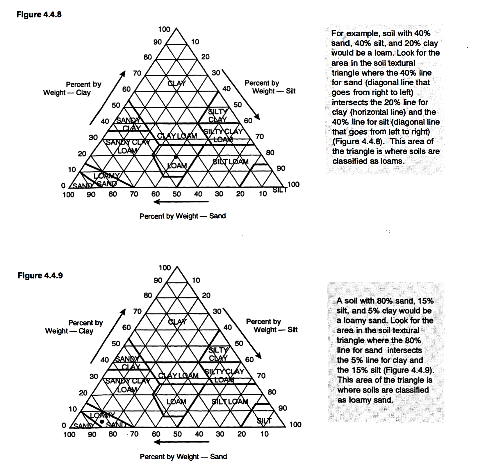
Soil Textural Class
Most soils are a mixture of the different soil separates. The texture of the soil in each soil horizon depends on the mixture of the soil separates. Every soil can be placed into one of twelve textural classes. To find the soil textural class, the percentages of sand, silt, and clay are plotted on a textural triangle. Figure 4.4.7 shows a soil textural triangle.
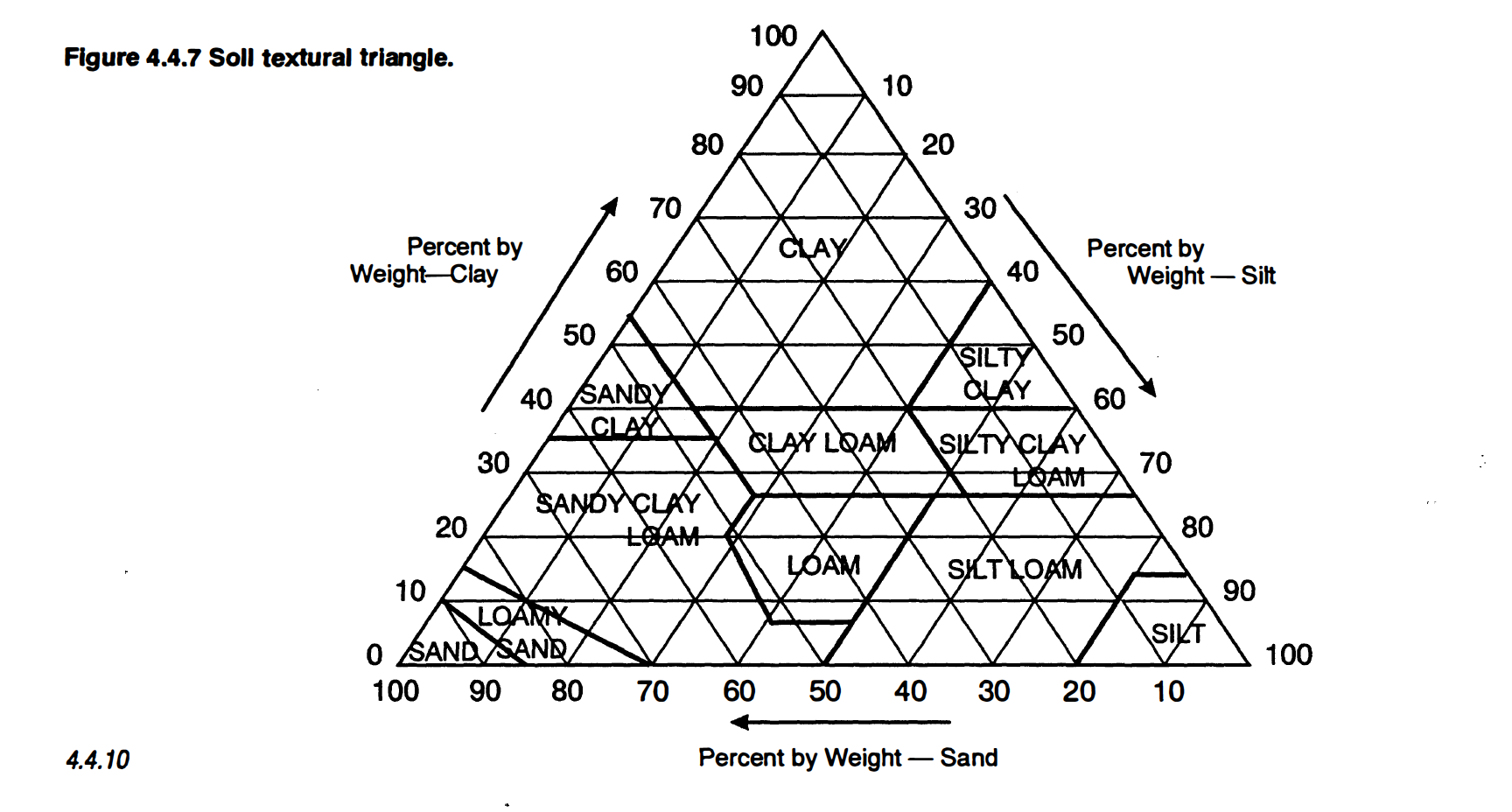
Soil textural triangle.
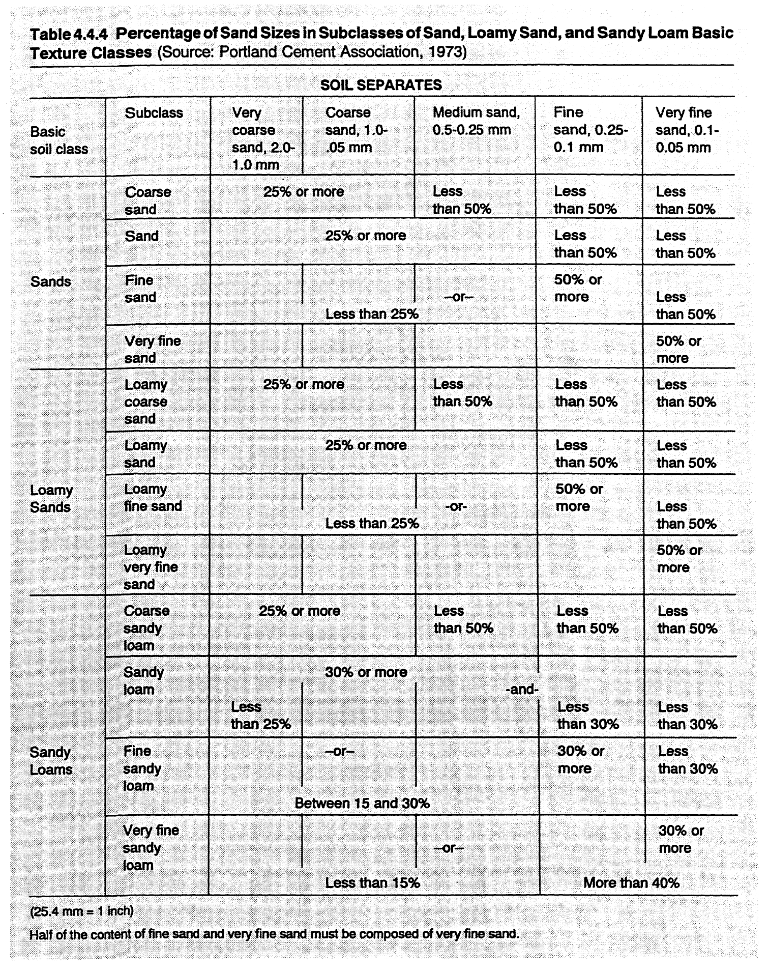
Percentage of Sand Sizes in Subclasses of Sand, Loamy Sand, and Sandy Loam Basic Texture Classes
The idea of grouping soils into textural classes was originally developed by the USDA to assist farmers with agronomic decisions. This textural classification system has been adapted for use in siting and sizing on-site systems because texture influences the permeability of the soil, or how fast the water moves through the soil.
Below are several examples of texture determination.

Soil texture is usually determined in the field by hand testing and can be confirmed by laboratory analysis. Section 45, Soil Texture, gives more details on testing soils.
In between the particles of sand, silt, and clay are spaces called voids. The voids are created because the soil particles do not fit together perfectly, leaving small, irregular spaces. Every soil has a certain percentage, normally between 35 and 50%, of its volume in voids. Soil voids are important because they determine the water and air movement possible within a soil.
Water and air flow into and out of a soil by moving through the void spaces. The ease with which water and air can flow through a soil is determined by the size of the voids, the number of voids in the soil, and how well the voids are connected to each other.
The amount, size, and connectivity of soil voids is determined, in large part, by soil texture. Therefore, soil texture becomes a critical factor determining the rate of wastewater flow through a soil horizon.
The size of the individual void spaces, in particular, has a strong influence on water movement through a soil horizon. For example, even though a clay-textured horizon will generally have more void space than a sandy-textured horizon, the movement of wastewater through a clay-textured horizon will be slower. This occurs because water can flow more quickly through the few large voids in the sand than through the many tiny voids in the clay-textured horizon. In order to account for these differences in wastewater flow, the on-site systems installed in the clay soil would require a much larger drainfield than a similar system located in a sandy soil.
In addition to the soil mineral solids, soils also contain organic matter. Organic matter consists of decomposed leaves, twigs, animal droppings, air and water. Most soils have organic matter contents that range between 1 % - 5% of the total soil weight. When the majority of the solids are mineral, soils are referred to as mineral soils.
Although organic matter makes up only a small portion of the soil, it is very important in determining several soil properties.
Organic matter partially determines how much water can be held by the soil.
Organic matter increases the surface area of a soil. Increased surface area is important in the retention of some of the wastewater constituents such as viruses, phosphorus, and ammonium.
Some soils, called organic soils, are primarily composed of organic matter with only a small amount of mineral solids. Organically stained soils (soils stained by decomposing organic matter) should not be confused with organic soils. Organic soils must have more than 20% organic matter to be classified as an organic soil.
As defined but he rules, organic soils are “those organic mucks and peats consisting of more than 20% organic matter (by dry weight) and 18 inches or greater in thickness.” Reference 15A NCAC .18A .1935(21)
Organic soils are always UNSUITABLE for on-site systems because these soils do not drain properly. Treatment and disposal fields cannot function in organic soils.
Soil is naturally gray to white in color when it is first formed. Over time, soil develops other colors. Soil particles become coated with inorganic substances or organic matter that is translocated or moved through the soil profile. For example, organic matter, such as decaying leaves and twigs, can be translocated from the soil surface downward to the A, B, and C soil horizons by rainwater moving downward through the soil. The decaying organic matter forms a brown or black coating on the soil particles so that the soil then appears to be brown or black. A coating of iron oxide on soil particles makes a red soil.
Soil color and soil wetness.
Soil color is a very useful tool for investigations of soils for on-site wastewater disposal because color can indicate the wetness of a soil. Soils that are too wet are inappropriate for siting an on-site system. While soil color cannot directly indicate the soil's suitability, soil color does indicate much about how wet the soil is throughout the year. Because of rainfall patterns and evapotranspiration, soils in North Carolina are drier during summer and fall and wetter during winter and spring. Figure 4.4.11 demonstrates the difference in water content between seasons.
For on-site systems, two problems are associated with wet soils:
Wet soils reduce the amount of air available for bacteria to treat the wastewater.
The high water table causes the wastewater to flow directly into the ground water without sufficient treatment .

Seasonal Moisture Relations
When soils are well aerated (when air can move freely through the void spaces), there is enough oxygen to oxidize iron to its highest state (Fe•3) and the soil has a uniform bright color. This bright orange color, due to oxidized iron, is the same color that occurs when metal rusts. In this state, the soil is aerobic and soil organisms use oxygen for their metabolism.
Soils that are saturated have a different color. When a soil is saturated, water replaces the air in the void spaces, oxygen cannot move through the soil, and the soil conditions become anaerobic, or without oxygen. Many anaerobic bacteria use iron, aluminum, or sulfate as a substitute for oxygen in their metabolism. Therefore, when a soil is saturated, iron is reduced by bacteria to Fe•2 and it becomes soluble in water and can be moved or translocated out of or
Soil that always remains saturated has a gray color since the iron is gone or is in the reduced, non-color state (Fe+2). Soils that have fluctuating wetness conditions, where the soil is saturated in the winter and spring and well aerated in the summer and fall, develop a distinctive splotchy color pattern of mixed rust-orange colors and gray colors that are called soil mottling ( described in more detail on the following page). Thus, soil color becomes a good indicator of moisture status.
Soil scientists use a very specific system - the Munsell color system - to standardize soil color descriptions. In the Munsell color system, each color is broken into three components: hue, value, and chroma.through the soil.
Hue is the basic color. Hue ranges from a value of 10R, which is a red soil, to
7.5 YR or 10YR, which are brown soils, to 5Y, which is a yellow soil.
Value is the lightness or darkness of the color.
Chroma is the purity or strength of the color. Natural gray starts at O and increases to a maximum of 8.
The Munsell color book is composed of color chips with various components of hue, value, and chroma. A soil sample is compared with color chips and the appropriate color designation that matches the soil is noted and recorded.
The matrix color is the dominant soil color of the horizon. Each matrix color can have a range of value, hue, and chroma.
Two Munsell charts are displayed in Figure 4.4.12. The left color chart displays various combinations of value and chroma for a soil with a 7 .5YR hue. The right color chart shows value and chroma combinations for a soil with a lOYR hue.Value and chroma designations are added to the hue. For example, the soil in Figure 4.4.12 could be described as 7.5YR 3/2 if it has a brown matrix color and a dark gray tinge. A soil designated as lOYR 5/1 is a gray soil.
If water cannot drain freely through the soil, then a color pattern called soil mottling usually develops. When a soil is repeatedly saturated for an extended period and drained, the iron compounds are biochemically reduced during saturation and then chemically oxidized when the soil drains. These conditions lead to a mottling pattern of bright rust- or orange-colored spots and dull graycolored spots on the background color of the soil. Soil scientists call the bright spots high chroma mottles and the dull spots low chroma mottles.
Mottles are described in terms of their abundance or number, size, and contrast compared to the background soil color. If greater than two percent of the soil contains mottles in chroma of2 or less, then the soil is generally considered wet (see Table 4.4.5). The abundance of mottles can be easily estimated using charts such as Figure 4.4.13.

Mottle Abundance, Size, and Contrast

Munsell charts.
In North Carolina, the only combination of abundance and contrast of mottles that designates a well-drained soil is few and faint. Any other combination of the mottling categories of abundance and contrast indicate potentially wet conditions.
The presence oflow-chroma colors, such as chroma 2 or lower, usually means that the soil is saturated part of the year. Often this happens when the water table rises during a wet season and saturates the soil.
The depth to low-chroma colors in a soil can help determine the depth to the seasonal wetness and the soil drainage class. This knowledge of soil wetness can be used in assessing the suitability of a soil for siting on-site systems.
As defined by the rules: “soil wetness conditions caused by a seasonal high-water table, perched water table, tidal water, seasonally saturated soils or by lateral water movement shall be determined by observation of colors of chroma 2 or less (Munsell color chart) in mottles or a solid mass.” Reference 15A NCAC .18A. 1942

Mottling abundance chart
Cautionary Note: In ascertaining soil wetness from soil color, care must be taken because in some soils, mottling can also be caused by natural variations in the parent material and notby soil wetness.
Other site characteristics can be used to indicate soil wetness. Vegetation and landscape position can both be used as an initial indicator of wet areas.
The SCS bas established criteria for seven soil drainage classes. The soil drainage class is a measure of bow wet the soil is during the year. Each drainage class is based on bow frequently and bow long the soil stays wet during a yearly cycle. See Table 4.4.6 for details on soil drainage classes.

Criteria for Soil Drainage Classes
Until 1992, soil scientists used chromas of 2 or less to signify wet soils. In 1992 the definition of a wet soil was broadened to include saturation, reduction, and morphological indicators because it was believed that color alone was not a specific enough indicator of soil wetness (Vepraskas, 1992). Under the new classification, wet soils must meet specified criteria for the following characteristics: the depth of saturation, the occurrence of reduction, and the presence of redoximorphic features. Redoximorphic features are iron nodules and mottles created by the process of reduction, translocation or movement, and finally by oxidation of iron and manganese (Figure 4.4.14).
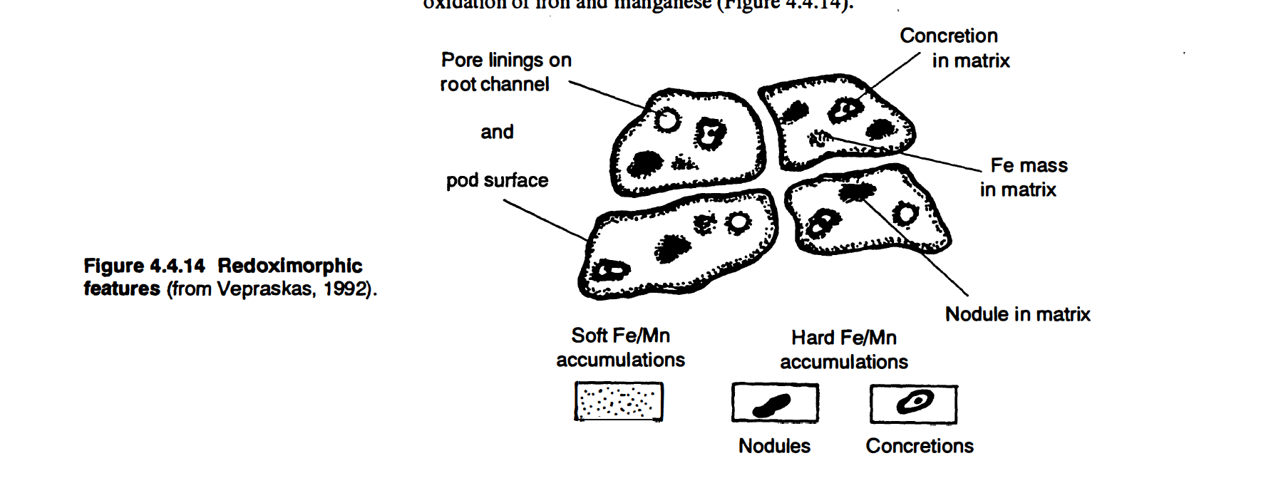
Redoximorphic Features
Redoximorphic features could have formed in the past and may not represent current soil wetness. For this reason, all three characteristics-saturation, reduction, and redoximorphic features-must be considered.
Saturation means that a soil is periodically saturated within the first two meters. This saturation may occur in the entire two-meter layer or in a portion of that layer.
Reduction no longer refers only to the absence of oxygen but now also includes the presence of reduced iron.
Redoximorpbic features include only mottles and iron nodules formed by the reduction, translocation, and oxidation of iron and manganese due to wetness. Mottles are a broader category of features that includes redoximorphic features, carbonate accumulations, organic stains, and parent material color variation.
Redoximorphic features are not currently used to determine soil wetness in the North Carolina on-site wastewater rules.
Soil structure is a measure of how the tiny particles in the soil group together, or aggregate, into units which give the soil its overall properties. Soil structure, as defined but he rules, is “ the arrangement of primary soil particles into compound particles, pets or clusters that are separated by natural planes of weakness from adjoining aggregates.” Reference 15A NCAC 18A.1935(42)
These soil aggregates, known as peds, are a mixture of all the soil components, such as sand, silt, clay, and organic matter. A per is defined in the rules as “a unit of soil structure, such as an aggregate, crumb, prism, block, or granule formed by natural processes.”
Ped dimensions range from fingernail to softball size.
Soils have different grades, sizes, and types of structure. See Table 4.4.7 for more details.
The grade of a soil structure refers to the stability of the ped, a measure of how easily the ped breaks into smaller units or forms larger units. The structural grade is described when the soil is in a moist state.
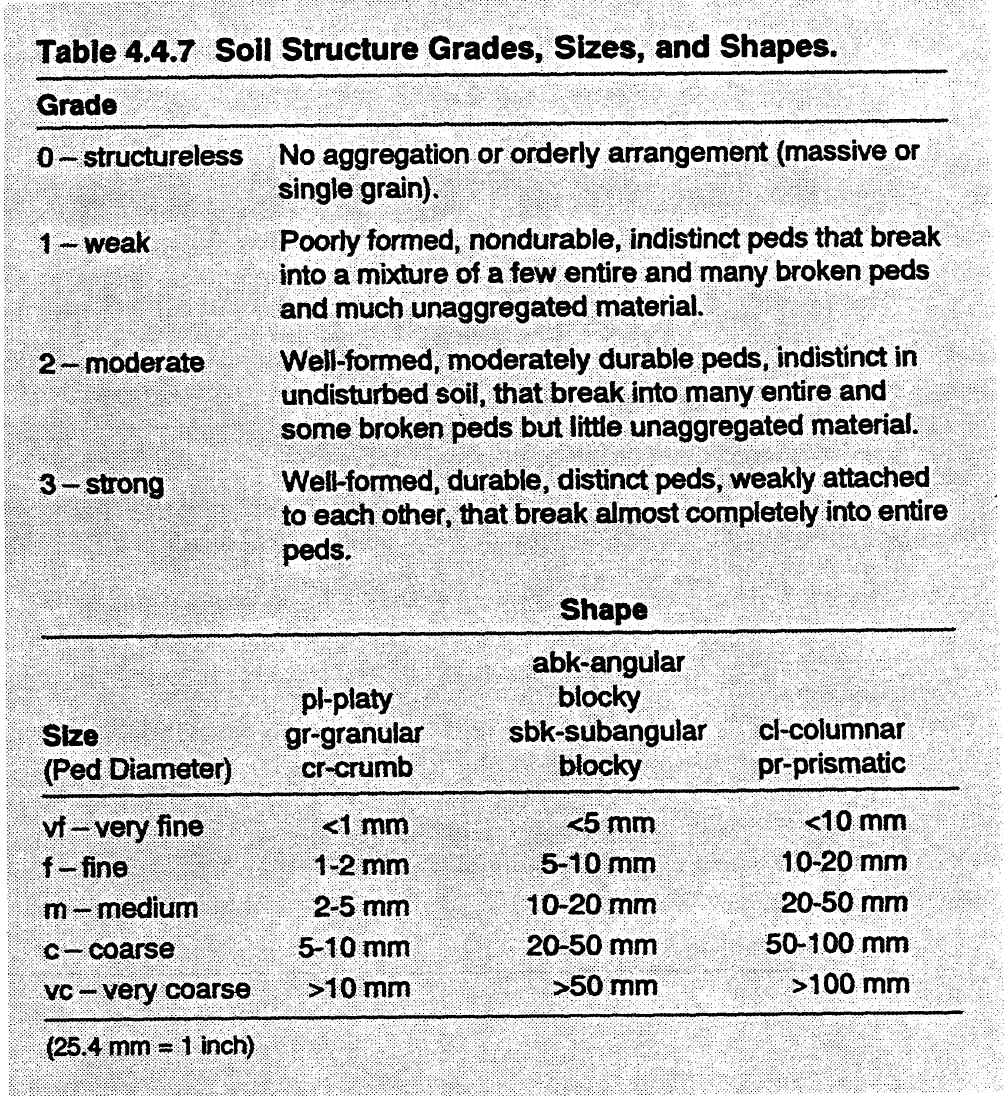
The size of a soil structure refers to the size of the individual peds in a horizon. The sizes range from very fine to very coarse. Most horizons have a mixture of ped sizes; therefore, the predominant ped size in a horizon is described.
The type or form of aped (structure) refers to the shape of the ped. Parent material and organic matter can affect the shape of peds. Soils with a type of clay mineralogy, known as 1 :1 mineralogy, produce sub-angular blocky peds. Soils with 2:1 mineralogy produce angular blocky peds in the summer and massive in the winter due to drying (shrinking) and wetting (swelling) .
Soil structure is an important characteristic for siting on-site systems because the structure of the soil affects the movement of water and sewage through the soil. Although the porosity is greater inside a ped, the majority of water flow is through the voids or cracks between the peds. Frequently, the only wastewater flow path in a soil that is sufficiently fast for wastewater disposal is between the peds.
Well-developed, fine peds can have an acceptable amount of wastewater flow through the voids between the peds.
The presence of peds is particularly important in clayey soils. If peds are too large in size (for example, greater than 1 inch or 2.5 cm), then wastewater will move too slowly (Figure 4.4.15).
Because soil structure affects wastewater flow, soils with certain structures, such as platy, massive, and prismatic structure, cannot be used to treat on-site waste effluent. Platy, massive, and prismatic structured soils can impede water flow, particularly in finer-textured soils.
In general, the size of the structural aggregates, or peds, increases with depth through the A and B horizons. In the C horizon the soil is massive and structureless, which means there are few or no structural aggregates. Because there are no peds present, wastewater flow through the C horizon can no longer be related to peds but is through the matrix.
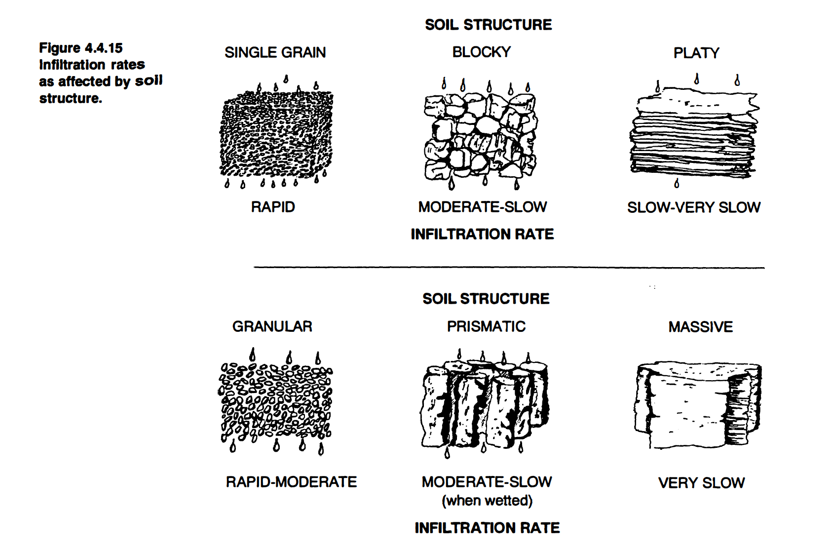
Infiltration Rates
Soil structure is not static. Peds can be changed by natural or man-made conditions such as: wetting and drying; freezing and thawing; physical activity of roots and soil animals; influence of decaying organic matter and of slimes from microorganisms and other life forms; modifying effects of adsorbed cations, clay films, iron oxides, and aluminum oxides; and construction activities. Examples of changed soil structure are presented below.
1. Movement of wastewater through the soil can change soil structure. Sodium causes soil particles to disassociate from each other. Wastewater high in sodium (for instance, as a result of brine from a home water softener) can cause soil peds to disperse or break apart, which in tum will decrease void volume between the peds. Wastewater movement will then be restricted because the voids are much smaller.
2. Construction of on-site systems in clay soils that depend on the preservation of voids between the peds must occur during dry weather. If construction occurs during wet weather, excavation of trenches can result in clays being smeared across the face of the soil. This smearing blocks the voids between the peds and impedes the movement of wastewater. If construction does occur when the soil is wet, rake the sidewalls to remove the smeared clay.
3. Compaction, or compressing the soil, changes the amount of the total void space and the distribution of the void sizes. This reduces the space available for air and water in the soil. Soil compaction generally reduces the structural porosity, the spaces between the peds, more than the internal porosity. When structural porosity is reduced, the volume and the continuity of the larger voids that transport water are reduced (Figure 4.4.16)..
Compacted soils should be avoided for on-site systems because a compacted soil may not be able to absorb enough sewage. Soils can be compacted by heavy machinery or by frequent trips of cars, trucks, or heavy earth-moving equipment over the soil.
Soil consistence is a measure of how well the soil sticks together and how resistant peds are to being ruptured or broken.

From the North Carolina Onsite Guidance Manual
Soils are characterized by the minerals and organic matter from which they are made and by the sequence of these mineral and organic layers. The type of soil layer and the order in which the soil is layered are extremely important in on-site systems because soil layers control the movement of wastewater through the soil into the ground water.
A soil consists of a number of layers roughly parallel to the earth surface. These layers are called soil horizons.
A soil horizon, as defined by the rules, “means a layer of soil, approximately parallel to the surface, that has distinct characteristics produced by soil forming processes.”
Soil horizons are identified by different morphological characteristics: texture, structure, color, or consistence. These are discussed in greater detail on page 4.4.8.
Soil scientists use a technical language in which each horizon is separated into one of six master horizons or layers. Master horizons are designated by the capital letters 0, A, E, B, C, and R where each master horizon indicates a certain set of properties in the soil. The sequence of horizons and horizon differentiation, for any given soil, is dependent on the soil forming factors. Figure 4.4.2 describes and demonstrates the six master horizons and their properties.
Every soil contains at least one master horizon, and some soils contain all six master horizons or layers. Usually a soil contains two or three master horizons.
The arrangement of horizons in the profile affects the rate of wastewater flow through the soil, the direction of flow (vertical or horizontal movement), and the amount of wastewater purification. Thus, the environmental health specialist must be able to identify the horizons present in the profile.
When horizons are transitional, that is, they have characteristics of both the overlying and underlying horizon, two master horizon symbols are used. For example, a BC horizon would indicate a transitional horizon that grades gradually from a B into a C but is more like a B horizon than a C horizon. On the other hand, a CB horizon would be more like a C horizon than a B horizon. When the "f' symbol is used it indicates that the transitional horizon contains identifiable pieces of both types of horizons. For example, a B/C horizon is indicative of a transitional horizon where the B and C horizons are intermixed and there is more B than C material. A C/B horizon would also be an intermixed transitional horizon but with more C material than B material. The BC or B/C horizons may be used for an on-site system if other soil factors are acceptable.
Master horizon designations can be modified by lower case letters that indicate subtle differences within a master horizon. Those symbols relevant to North Carolina soils are included in Table 4.4.1.
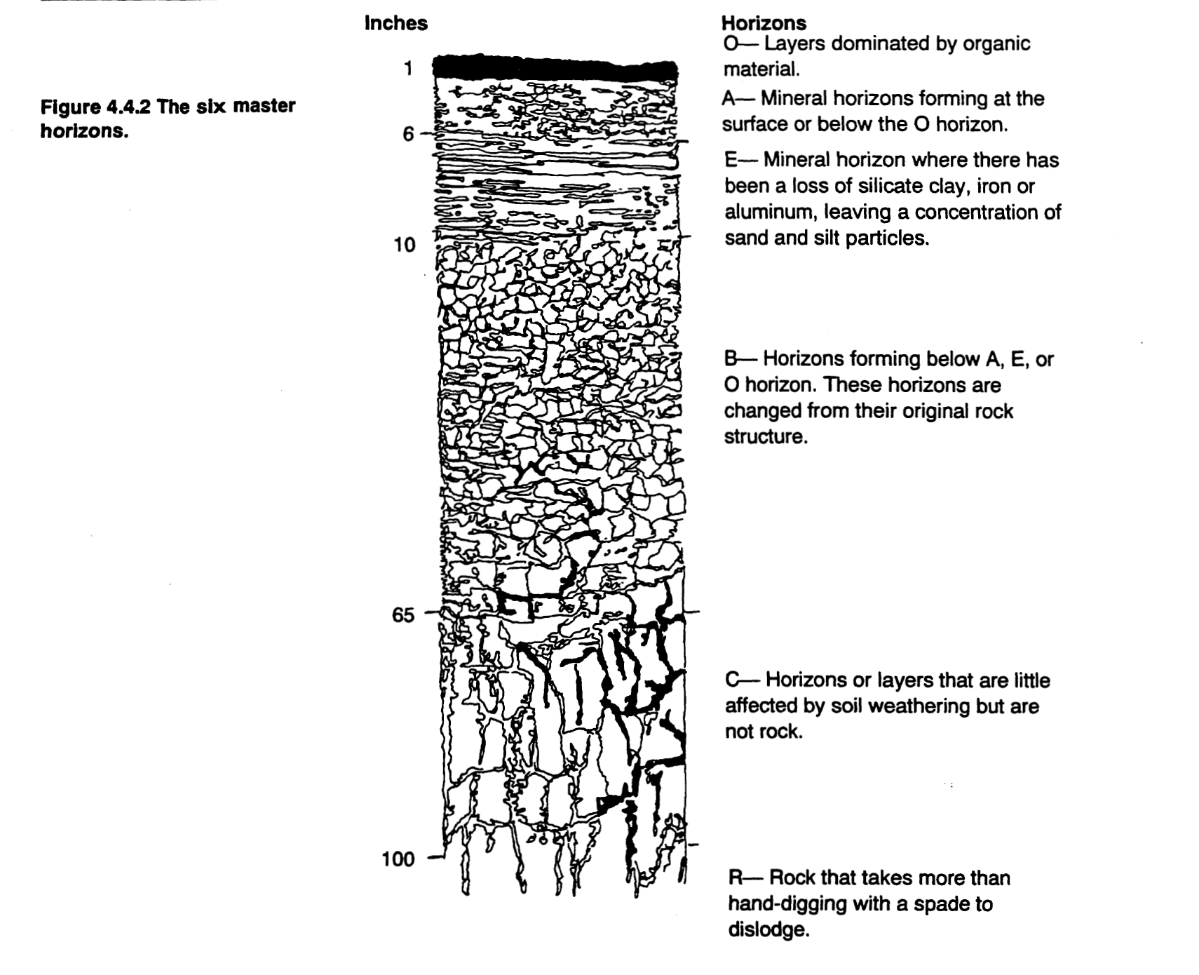
The six master horizons.
Some horizons allow water to flow through easily; other horizons obstruct water flow. Horizons which impede water flow are referred to as restrictive horizons. If a soil contains a restrictive horizon, the depth at which this horizon is located determines whether this soil is SUITABLE for an on-site system.
As defined by the rules (Ref. 15A NCAC 18A. 1935 (33)
“A restrictive horizon means a soil horizon that is capable of perching ground water or sewage effluent and that is brittle and strongly compacted or strongly cemented with iron, aluminum, silica, organic matter, or other compounds. Restrictive horizons may occur as frangipanis, iron pans or organic pans, and are recognized by their resistance in excavation or in using a soil auger”.

Subordinate Distinctions within Master Horizons
Soil horizons can also be described by depth, thickness, and boundary conditions, as shown in Table 4.4.2.
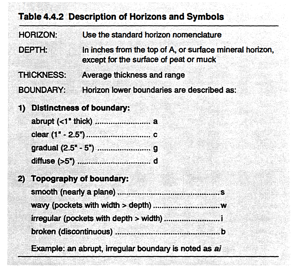
Description of Horizons and Symbols
Generally, a soil is composed of more than one horizon. If a hole or pit is dug in a soil, the horizons are uncovered for viewing. This vertical cross section of soil, where all horizons are revealed, is called a soil profile.
Soil profiles, showing typical arrangements of horizons for five representative soils in North Carolina, are presented below (Figure 4.4.3). These five soil profiles are but a few examples of the over two hundred types of soil profiles found throughout the state.
Soils can be grouped and classified based on the arrangement of soil properties within each layer in the soil profile. These properties include texture, temperature, wetness, mineralogical classes, organic matter content, and other characteristics.
Soil profiles that have a specific arrangement of horizons with specific characteristics in each horizon belong to a soil series. All soils in a soil series have similar profile characteristics. Each soil series will have developed from the same parent material with the same combination of weathering processes. The following concepts are helpful in understanding soil series.
Soils within the same soil series should be more alike and behave more similarly than soils in different soil series.
Soil series are generally named for a town or region near the location where the soil series is first described.
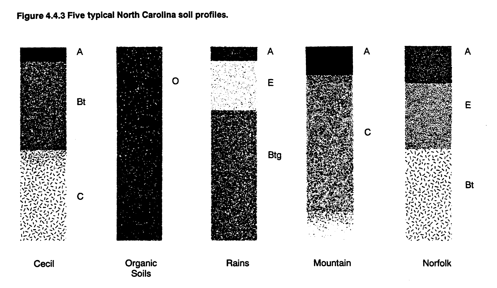
Five typical North Carolina soil profiles
Soil series are strongly associated with relief or topographic location. This is because the soil-forming processes and the other soil-forming factors (parent material, time, climate, and organisms) in a region are the same for one type of topographic location and so tend to form one or a few soil series from the same parent material. Catenas are a good example of the effects of topographic location on the landscape. A catena is a group of related soils in a topo-drainage sequence. A representative North Carolina Coastal Plain catena consists of five soil series: Norfolk, Goldsboro, Lynchburg, Rains, and Pantego. These soils are related by their topographic positions or relief. Relief affects drainage and thus the accumulation of organic matter. Norfolk soils are the most well drained, whereas Pantego soils are very poorly drained.
Soils are mapped as soil series. Because a soil series tells us about the properties of a soil, soil maps give a great deal of information about the soil and, consequently, they give a good idea of how an on-site system will function in a location with a given soil series. In North Carolina there are over 250 mapped soil series. Figure 4.4.4 is a representative soil map from the Piedmont area of North Carolina.
Because the scale of soil maps is generally greater than the area of an on-site system, soil maps should only be used in the initial survey of the area. The only reliable method for siting an on-site system in North Carolina is a thorough site and soil evaluation done by qualified specialist at the actual site. The site and soil evaluation must include a thorough evaluation of the soil morphological properties in the soil horizons at that location.
In North Carolina, each potential location for an on-site system is required, by law, to have a site and soil evaluation. Ref: G.S. 130(A)-336(b)
From the North Carolina Onsite Guidance Manual
Soil forming processes include additions to soil bodies, such as sand blown up onto a sand dune; losses from soil bodies, such as soil erosion; translocations within a soil body, such as downward movement and accumulation of clay-sized particles in the subsoil; and transformations of material within a soil body, such as weathering of sand-sized mica particles into clay-sized kaolinite minerals.
The five soil-forming factors are parent material, relief, organisms, climate, and time.
Parent material is the rock or other matter which degrades into soil. Soils are very reflective of their parent material. For example, a soil developed from granite rock will always have a coarse texture and a relatively low pH.
Relief refers to both the slope of land and the aspect (the direction in relation to the sun) of the surface. The most obvious influence of relief is through slope. Slope affects losses and additions and thus causes changes in soil depth.
Organisms refer to the biological agents such as plants, fungi, and microorganisms that break down parent material into soil particles and also contribute organic matter to the soil. For example, the distribution, quantity, and type of organic matter in a soil developed under prairie vegetation is very different from a soil developed under forest vegetation.
Climate encompasses rainfall and snowfall, evaporation, and temperature. Climate controls some chemical and physical reactions and it can also affect the type of organisms in and on a given soil. Weathering of a soil is either hastened by a hot, moist climate, or retarded by a cold, dry climate.
Time is an important soil-forming factor because it modulates the other four factors. For example, a younger soil has had less time for its parent material to be changed, and for climate, relief, and organisms to affect the soil forming processes.
From the North Carolina Onsite Guidance Manual
Soil is defined differently by groups that use soils for varying purposes.
For the purposes of site and soil investigations for on-site systems in North Carolina, the most important definition is that contained in the Rules for Sewage Treatment and Disposal Systems:
“The naturally occurring body of porous mineral and organic materials on the land surface. Soil is composed of sand, silt, and clay sized particles that are mixed with varying amounts of larger fragments and some organic material. Soil contains less than 50 percent of its volume as rock, saprolite, or coarse-earth fraction (mineral particles greater than 2.0 millimeters). The upper limit of the soil is the land surface, and its lower limit is ‘rock,’ ‘saprolite,’ or other parent materials.”
Engineers define soil as "any unconsolidated material composed of discrete solid particles with gases and liquids between" (Sowers, 1979).
Soil, as defined by geologists, is "that material which has been so modified and acted upon by physical, chemical, and biological agents that it will support rooted plants" (AGI, 1976).
Soil, as defined by soil scientists, is a naturally occurring, three-dimensional body that has developed at the earth's surface as a result of soil-forming processes: additions, losses, translocations, accumulation, and transformations, as influenced by the five soil-forming factors: parent materia relief, organisms, climate, and time.
Many of the criteria that are used to determine soil suitability for on-site systems come directly from soil characteristics defined by the Soil Conservation Service (SCS) in Soil Taxonomy Handbook (1993) and in the Soil Survey Manual (1994).
From the North Carolina Onsite Guidance Manual


