The volume of wastewater that can be treated and disposed of by an on-site system is extremely important to the system user and to environmental health specialists. An on-site system that fails because too much wastewater is applied is not only a problem for the user and environmental health specialist, but is also a danger to the public health. On the other hand, oversized on-site systems are expensive and may not be the best use of land.
Estimating System Loading Rates
The loading rate of an on-site system is the amount of wastewater applied to a square foot of soil per day. This rate depends on a number of factors, including the long-term acceptance rate of the soil at the infiltrative surface, the type of onsite system, and the contents of the wastewater.
Detailed knowledge of the site is necessary to keep the system loading in a safe range. This section presents ideas for determining the loading rate for an on-site system.
Long-Term Acceptance Rate of a Soil
The long-term acceptance rate (LT AR) is the amount of wastewater that can be applied each day over an indefinite period of time to a square foot of soil such that the effluent from the on-site system is absorbed and properly treated. In the rules, LT AR and loading rate are the same.
The LT AR is determined by a number of factors. Certainly, the rate effluent can move through the most hydraulically limiting soil horizon has a great effect on the LTAR. However, the type ofbiomat that forms at the infiltrative surface and the type of system also affects the LTAR. A specific LTAR is based on the total evaluation of the soil and site.
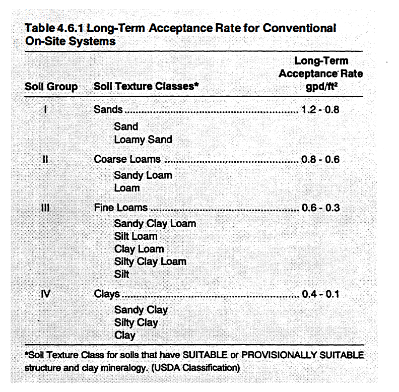
□ Table 4.6.1 illustrates bow soil texture affects the range of values for LTAR for conventional systems. The loading rate of Group I soils can be as much as 10 times that of Group N soils.
□ An example of how the LT AR range is changed for some modified wastewater systems can be seen by comparing Table 4.6.1 and 4.6.2. For the same texture, the LTAR range for wastewater effluent application is always greater for a conventional on-site system installed in the soil solum (A, E, or B horizon) than for a system installed in saprolite. The reason for this difference is that saprolite materials usually have lower hydraulic conductivity than solum horizons of a comparable texture (Amoozegar et al., 1993).
□ For conventional systems or modified conventional systems, the LT AR is the rate per day that wastewater can be absorbed through the bottom of the infiltration trenches and underlying horiwns. For low-pressure pipe (LPP) systems, the LTAR is the rate per day that wastewater can be absorbed through the entire drainfield area (trenches plus the area between the trenches).
Conventional On-Site Systems Loading Rates
For conventional on-site systems the LT AR is based upon the most hydraulically limiting soil horizon within 3 feet of the soil surface or one foot below the trench bottom, whichever is deeper. Long-term acceptance rates for conventional on-site systems are presented in Table 4.6.1 for the four soil groups.
If grease accumulation will be a problem, then the LTAR for any soil group cannot exceed the mean rate of application. For example, if a food service or meat market facility was planned for a site with a clay loam textured soil, then the maximum wastewater loading rate possible for the site would be 0.45 gpd/ft2.
For facilities where there is data from comparable facilities that indicate the grease and oil content of the effluent will be less than 30 mg/1 and the chemical oxygen demand is less than 500 mg/1, an LTAR up to the maximum for the applicable soil's textural group can be used. Otherwise, if a significant pretreatment system will be used at a business or place of public assembly that can assure consistent reduction of the wastewater strength to that of a typical single family home, then a loading rate greater than the mean for that soil group could logically be considered for that site. However, this would require a special application under rule 15A NCAC 18A.1948(d) by the owner to the Health Department.
Using long-term acceptance rates to calculate the treatment and disposal field size. The following calculation of treatment and disposal field area is for a conventional system.
The amount of effluent that is expected to enter a septic tank each day is based on the type of facility, as stated in 15A NCAC 18A.1952(b)(l). In this example, a three-bedroom house will be built on the site. The daily flow rate into the septic tank is designed to be 360 gallons per day for the whole house, or 120 gallons per bedroom per day.
The on-site system is to be sited on a soil whose most restrictive textural horizon within a foot of the trench bottom ( or 3 feet from the ground surface) is Group IV. The LT AR for this soil texture ranges from 0.4-0.1 gpd/ft2 - For the purposes of this example we will select a LTAR of 0.4 gpd/ft2
The daily flow is divided by the LTAR to determine the trench bottom area: 360 gpd divided by 0.4 gpd/ft2 equals a trench bottom area of 900 ft2.
In order to determine the length of trench from the trench bottom area, the trench bottom area is divided by the trench width: 900 ft2 divided by a 3 ft trench width equals 300 linear feet of trench.
Total drainfield are for a conventional septic system
If the slope is uniform and there are to be three trenches, then each trench would be 100 feet long. The trenches must be on 9 foot centers since the trenches are 3 feet wide. (Note: the center to center spacing equals 3 times the design trench width.) Therefore, the minimum total area for installation of the nitrification area is 2100 ft2: the sum of 1.5 ft + 9 ft + 9 ft + 1.5 ft times 100 ft long which equals 2100 ft2 (Figure 4.6.1).
Modified Conventional On-Site Systems
For sites where the distance between the soil surface and a limiting soil condition of soil depth or soil wetness is less than 36 inches, the site can be reclassified to PROVISIONALLY SUIT ABLE for the installation of a modified conventional system. Using shallow placement of the treatment and disposal field trenches, the most hydraulically limiting soil, rock, or saprolitic horizon within at least 24 inches from the soil surface or 12 inches below the trench bottom, whichever is deeper, is used to determine the LTAR.
On-Site Systems Installed in Saprolite
Long-term acceptance rates have also been determined for saprolite that has been deemed acceptable for on-site system installation as stated in rules ISA NCAC 18A1956(6).
For on-site systems installed in saprolite, the LT AR for the site is the LT AR of the most hydraulically limiting saprolite within a depth of 2 feet below the trench bottom. See Table 4.6.2 for values of LTAR for saprolite.
Like conventional on-site systems, the LTAR for saprolite is related to the textural class of the saprolite. However, with saprolite, only two textural groups are acceptable, Oass I and Class II saprolites, which are subclassified as sands, loamy sands, sandy loams, and loams.
Total daily flow for on-site systems installed in saprolite cannot exceed 1,000 gallons.
Using long-term acceptance rates to calculate the treatment and disposal field size.
Calculations for the treatment and disposal field area are the same for saprolite as they are for a conventional system, except the loading rates are lower. Use the appropriate long-term acceptance rates for Oass I and Class II texture saprolite in Table 4.6.2.
Gravelless Trench Systems
For gravelless trenches, including prefabricated, permeable block panel on-site systems and large diameter pipe systems, the LTAR is determined from the appropriate table (Table 4.6.1 or 4.6.2), but is restricted to never being greater than 0.8 gallons per day per square foot.
Low-Pressure Pipe On-Site Systems
If a low-pressure pipe on-site system is used at a particular site, then the wastewater loading rate for that site must be matched to the LT AR for this type of system. The LTAR selected is based on the most limiting soil horizon that occurs-within 2 feet of the soil surface or one foot below the trench bottom, whichever is deeper. The LTARs for low-pressure pipe on-site systems are presented in Table 4.6.3 for the four ii groups.
Using long-term acceptance rates to calculate the treatment and disposal field size.
Unlike conventional systems where the loading rate is based on the trench bottom area, the loading rate for a low-pressure pipe system is based on the total area of the treatment and disposal field.
The following calculation of treatment and disposal field area is for a low-pressure pipe system.
The estimated LTAR is 0.15 gpd/ft2 for this site where a low-pressure pipe on-site system is to be installed. 360 gpd of wastewater effluent will flow daily to the treatment and disposal field. The amount of treatment and disposal field area needed is calculated as 360 gpd divided by 0.15 gpd/ft2 which equals a total of 2400 ft2. If the trenches for the drainfield are spaced a distance of 5 feet from each other then the total trench length needed is 480 feet, or 2400 ft2 divided by 5 feet equals 480 feet. Thus, keeping the trenches under 70 feet in length, 8 trenches each 60 feet long, are necessary to handle the daily amount of wastewater flow (Figure 4.6.2). Again, this example is for a site with a uniform slope.
From the North Carolina Onsite Guidance Manual


