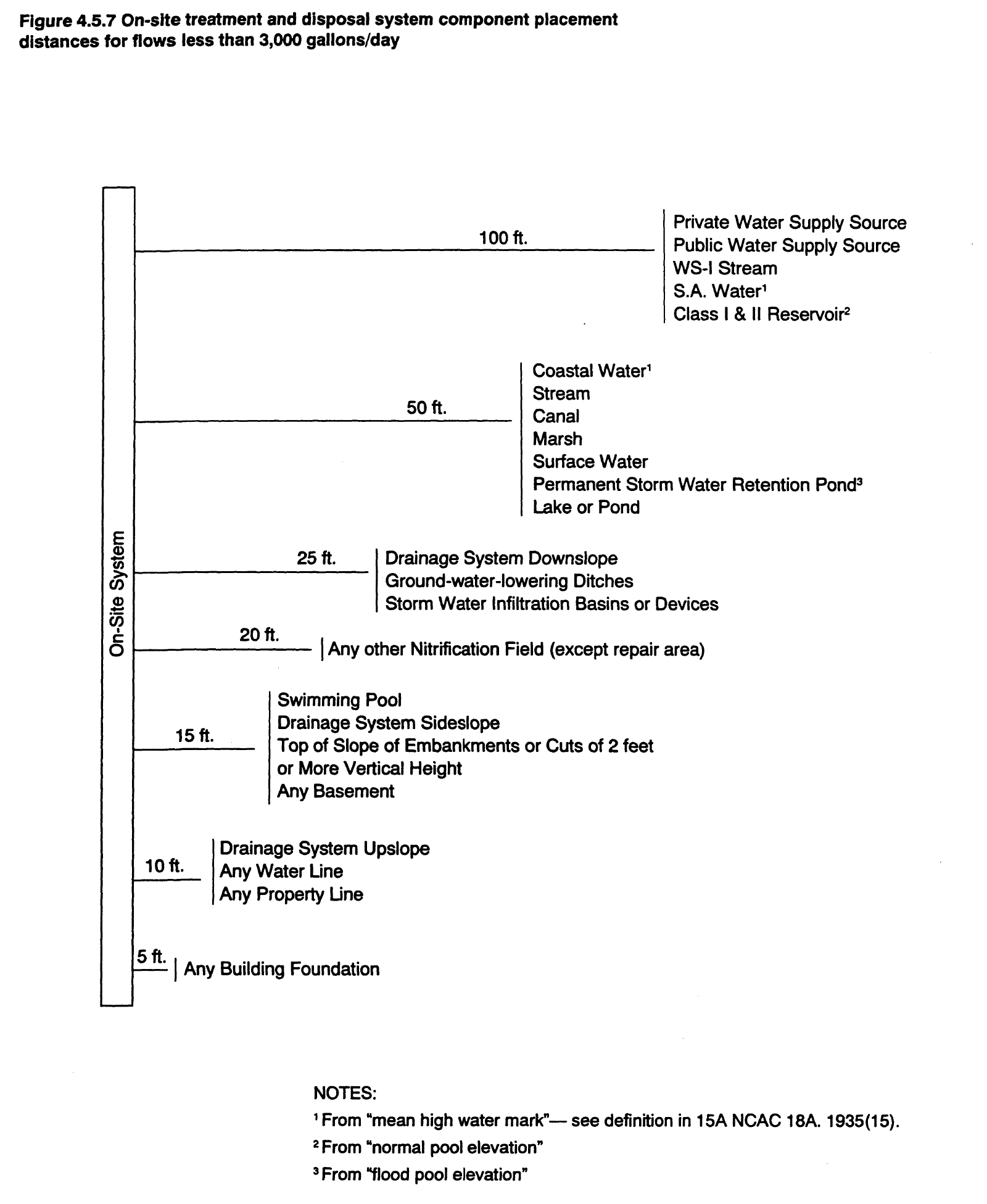
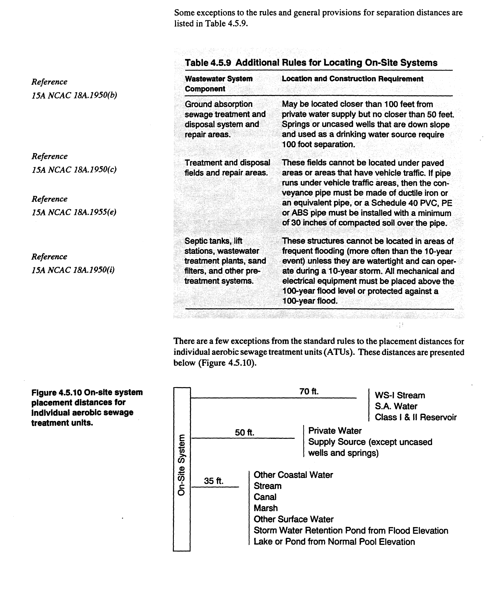
Available space for on-site systems depends on both the area of acceptable soil and site conditions and the required separation distances between the on-site system and buildings, water supplies, and other structures.
On-site space needed.
Sites for on-site systems must be large enough to allow installation and proper functioning of the systems. There must be enough area for the treatment and disposal field so that the system has long-term reliability.
In addition to the area needed for the treatment and disposal field, sites must be large enough area for a repair or replacement system that is set aside. The repair area would be used to install another treatment and disposal field if the original treatment and disposal field fails.
In the rules, the definition of the repair area is “an area, either in its natural state or which is capable of being modified, consistent with these rules, which is reserved for the installation of additional nitrification fields and is not covered with structures or impervious materials.”
The size of repair areas must conform to the rules for the design criteria of conventional sewage systems (15A NCAC 18A.1955), modification to septic tank systems (15A NCAC 18A.1956), or for design of alternative sewage systems (15A NCAC 18A.1957). For example, the initial system may be a conventional septic system with 4 trenches, 9 feet on center and 80 feet long and the replacement may be a pressure distribution system with 10 trenches, 5 feet on center, and 80 feet long. The repair area must also conform to the necessary setbacks. The improvement Permit must designate the original system layout, repair area, and type of replacement system.
There are exceptions to the repair area criteria above. If a site or tract of land meets all of the following criteria then it is exempt from the repair area space requirement:
The lot or tract of land was on record with the Register of Deeds at the court house on January 1, 1983.
The lot is of insufficient size to satisfy the repair area requirement.
A system of no more than 480 gallons is to be installed.
Lots exempt from the replacement system are requirement must still reserve the maximum feasible area for repairs or expansion of the initial system.
Horizontal distance placement requirements.
A site must have enough space to install the onsite system and to keep a separation between the system and certain features or structures. On-site systems must be set back certain distances from water supply sources, streams, lakes, drains, buildings, property lines, and other features. These minimum setback distances are to protect water wells, streams, and homes from pollution by the on-site system, allow for area to install the system, and space for the treatment and disposal of wastewater.
Additional Evaluation Factors
There are a number of situations where other factors, in addition to the above six site factors, must be considered.
High-capacity wells.
All pumping wells create a cone of influence, an area around the well where the ground water level is lowered by the withdrawal through the well. High-capacity wells, such as community, municipal, and industrial water supply wells, pump more water and have much larger cones of influence than household wells. These large cones of influence must be considered when locating on-site systems. Thus, on-site systems may need to be located much farther away from large wells than the required 100 feet, as shown in Figure 4.5.7.
Large on-site systems.
For on-site systems discharging more than 3,000 gallons per day, certain information must be collected to predict the height of the water table mound below the treatment and disposal field and the flow rate of the wastewater from the treatment and disposal field trenches. Soil borings to depths greater than 48 inches, permeability and hydraulic conductivity measurements, and water level readings must typically be collected. If these measurements indicate that the water table will not remain two or more feet below the treatment and disposal field or that the wastewater will rise to the surface, the site must be classified as UNSUITABLE. More detail on conducting site evaluations for large systems can be found in Section 4.6.
Hydraulic conductivity measurement techniques and other tests in relationship to some soil morphological characteristics. Hydraulic conductivity is the measure of the rate water moves through the soil. The rate of water movement through a soil is influenced by the texture, structure, and mineralogy, because these soil morphological characteristics determine the size and the connectivity of the pores, which in tum determines the speed of water movement.
Hydraulic conductivity measurements for determining site suitability for onsite wastewater systems are used in two specific situations in North Carolina:
For large systems where the flow to a single nitrification field is more than 1500 gallons per day and
For the design of artificial drainage systems used to modify sites for on-site systems.
In most situations, the usual site evaluation is enough to determine the suitability of the site or lot for on-site systems. For sites located on benchmark soils (soils that are typical to North Carolina), additional information on hydraulic conductivity is available.
Hydraulic conductivity tests. Determining hydraulic conductivity requires a proper test method. Many hydrau}ic conductivity tests have been devised and are in use in different areas. A good source for information on hydraulic conductivity tests is the article by Amoozegar and Warrick, 1985, in Appendix B.
The two methods most commonly used in North Carolina when soil hydraulic conductivity measurements are necessary are the constant-head permeameter test and the auger-hole pump out test.
□ Constant-head permeameter test. The constant-head permeameter, also called the shallow well pump-in method, is a common technique used to measure saturated hydraulic conductivity. This test works best where the water table is relatively deep. A source of water is required to saturate the soil for this test. See the publication by Amoozegar and Warrick, 1985, or Appendix 2, for more information on constant-head permeameter tests.
■ To run the test, a hole is bored to a desired depth and enough water is poured into the hole to maintain a certain depth of water in the hole, usually 6 inches (for a 2.5-inch diameter hole). After a while, the flow rate of the water out of the hole through the soil will be constant. This flow rate should be measured, along with the diameter of the hole, the depth of the water in the auger hole, and the distance between the bottom of the hole and any restrictive layers. Equations provided in Appendix B should be used to calculate saturated hydraulic conductivity.
□ Auger-hole pump-out test. The auger-hole pump-out method, or auger-hole method, is the most commonly used test to measure saturated hydraulic conductivity where the water table is near the surface. More details on this test can be found in the article by Amoozegar and Warrick, 1985, in Appendix B.
■ In this test, a hole is dug below the water table, using a soil auger to minimize soil disturbance. The hole needs to fill with water and be pumped out several times before the actual test. When the test begins, the ground water is allowed to rise in the hole to the level of the water table. Then, the water is pumped out of the hole and the rate at which the water rises in the hole is measured.
■ To calculate the saturated hydraulic conductivity, the depth of the water in the hole , the diameter of the hole, and the distance between the restrictive layer below the hole and the bottom of the hole must be determined. Several different calculation techniques can be used. See Appendix B for more information on this test.
□ Other methods. As mentioned above, there are a number of methods for determining hydraulic conductivity. In Methods of Soil Analysis, Amoozegar and Warrick have separated shallow water table methods from deep water table methods. The methods described by Amoozegar and Warrick are listed below. More information can be found in Appendix B.
■ Shallow water table methods include the auger-hole pump-out method, the · piezometer method, and other techniques.
■ Deep water table methods are the double-tube, the shallow well pump-in, the cylindrical permeameter, the infiltration-gradient, and the air-entry permeameter methods.
Compilation of Site Information
Because North Carolina uses site evaluation to determine site suitability, it is essential to evaluate all six factors-slope and landscape position, soil morphological characteristics, soil wetness, soil depth, restrictive horizons, and available space--and to compile them into a suitability rating.
If the ratings are the same for all six evaluation factors, then that rating is the site's classification. For example, on a site where each individual factor is designated as SUITABLE, the site should receive a SUITABLE classification.
If some of the site evaluation factors are different, then the most limiting factor that cannot be corrected determines the overall site suitability classification. If, for example, one of the six factors is deemed UN SUIT ABLE and cannot be corrected, then the site will be classified as UNSUITABLE. Several examples of uncorrectable limiting factors are listed below:
■ The setbacks from existing wells on the property or on adjacent property are not far enough away (as specified in the rules) from the proposed onsite system.
■ A dissected toe slope or depression is part of the site's landscape-position.
■ The slope is greater than 65%.
■ Rock or plinthite is found at a depth less than 36 inches.
■ The clay mineralogy is 2:1.
From the North Carolina Onsite Guidance Manual


